 |
|
Protein Crystallography Course
|

Course Homepage
Basic:
1
2
3
4
5
6
Advanced:
7
8
9 10
11
12
13 14
15
16
17
18 19
20
21
22
Fitting, Refinement & Validation
Philip R. Evans, MRC Laboratory of Molecular Biology, Hills Road,
Cambridge UK
pre@mrc-lmb.cam.ac.uk
This talk is heavily biased towards the program O. Sections of this
document which specifically refer to methods and commands in O are in italic
script.
The problem
Electron density maps, whether from an initial structure determination
(eg by MIR, MAD) or during refinement, are not self-explanatory. They need
human or machine intelligence to interpret.
Problems with maps may be divided into three categories: maps are :-
-
blurred (resolution)
-
wrong (errors)
-
unlabelled (what is that blob?)
The task of electron-density fitting is to interpret the electron-density
maps in the light of chemical knowledge, of basic stereochemistry, the
chemical sequence, and the nature of any bound ligands (if known)
Resolution
At very high resolution, individual atoms can be fitted, and the problem
is join-the-dots. Labelling remains a problem, but a relatively easy one.
1Å resolution

At the other extreme, large chunks must be fitted at one time. Alpha-helices
are clear at 6Å resolution, but beta-sheets are not. At lower resolutions
than about 8Å, only whole molecules can be placed.

6Å resolution
At 1.0Å, there is no problem fitting individual atoms (and the
N atom is bigger than the carbons). At 2.5Å the ring is easily fitted,
at 3.0Å less easily, and at 4Å the fit is very uncertain.
1.0Å
2.5Å
3.0Å
4.0Å
The size of the fitted objects depends on the resolution:
-
High resolution: atoms
-
Medium resolution: residues, sidechains
-
Low resolution: secondary structure elements, molecules
Overview of fitting: programs, strategies
There are now a number of programs which automate some or all of the process:
these and others are under active development, and will undoubtedly improve
in the future. This talk concentrates on manual building, in particular
using O, and will not discuss these automatic methods.
Automatic fitting programs
This is an active area, and there are undoubtedly other programs that
I am unaware of.
Fitting fragments (helices, sheets, molecules etc):
ESSENS
Kleywegt
fffear
Cowtan
These methods could be a useful start to interpretation
Autotracing
warpNtrace
Lamzin, Perrakis, Morris
Quanta
Oldfield et al.
In favourable cases at least (warpNtrace needs highish resolution),
these can build most of the structure
Manual fitting
Model building is too complicated to do in one step, but it may be broken
down into stages. Remember that what you are constructing is a model,
a hypothesis, and that it may make sense to build multiple models
for parts (or all) of the structure. Anything can be changed. What follows
here is one approach, proposed by Alwyn Jones and used successfully for
many structures. In the discussion, I assume a polypeptide: polynucleotides
can be fitted in a similar way in principle, but the programs are less
well developed.
-
Using the skeletonised map, trace the polypeptide (polymer) chain, as far
as possible (there may be gaps). This provides an outline path for subsequent
stages.
-
Identify at least one point in the sequence using the density or known
markers.
-
Place CA atoms, labelling residues with their correct sequence number and
identity if possible. If the place in the sequence cannot be determined,
build poly-Ala
-
fill in other atoms according to known stereochemistry and a library of
common backbone conformations, add sidechains in common rotamer conformations.
-
adjust each residue to improve the fit to the density: manual or (semi)automatic
fitting, keeping or reimposing stereochemistry
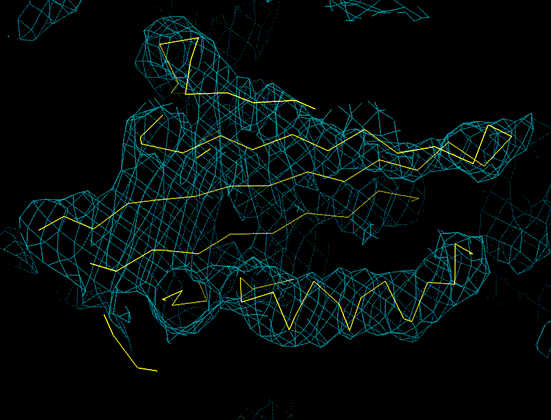
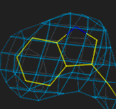
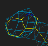
Tracing the chain with a skeleton (bones)
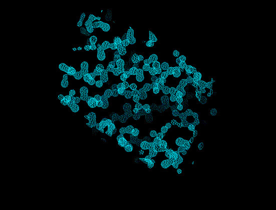
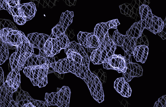
An electron-density map in eg the conventional chicken wire representation
is too complicated to be able to see the larger features. The skeleton
is a simpified representation which allows the whole molecule and major
secondary structure features to be seen at once, to get an overall view
of the structure.

Too much detail
Simpler
A first examination of a large volume of space (several unit cells)
often allows definition of the region of the cell which covers one molecule:
this part of the cell can then be cut out for future use (in O, it is
inconvenient if the chain trace runs off the edge of the skeletonised map,
so the initial volume need to be chosen generously and carefully).
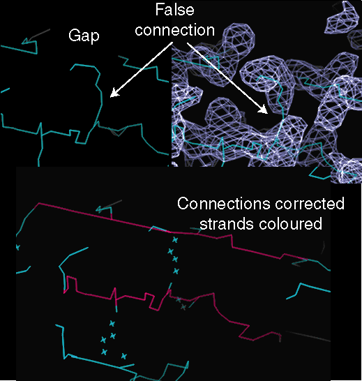
The skeleton can then be edited to produce a continuous coloured trace
approximately along the mainchain. The trace will principally be used as
a visual guide, so there is no need for the line to follow the chain accurately.
The edit operations are
-
break bond: break false connection
-
make bond: make missing connection
-
set "bone level": colour a line
O classifies bone atoms as classes 1 to 10, each assigned a different
colour. Initially all atoms are assigned either to "mainchain" (class 3,
cyan) if they are in a continuous line, or otherwise "sidechain" (class
2, red). You can use the other classes for any convenient purpose, to indicate
which regions have been examined, and to mark which parts of the chain
have been traced.
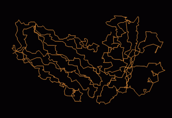
Final trace of whole molecule
The bone trace fits the final CA trace
Positioning the sequence on the trace
A. Markers:
-
Recognisable aminoacids
-
SeMet
-
Hg - Cys
-
active site, prosthetic groups etc
B. Direction:
Easiest to see in alpha-helix
Direction is not obvious in the skeleton
Sidechains point towards N-terminus (Christmas tree)
Helix direction is visible in map
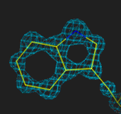
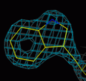
Direction is less clear in beta-sheet, unless the resolution is high
enough to see the carbonyl groups clearly (this is 1.8Å resolution)
C. Slider
If no clear markers can be found, it is possible to find likely
positions by guessing residue types, based on small/medium/large classification,
and comparing a short segment of guessed sequence with the real sequence,
using the same sort of algorithm that is used in sequence matching, but
with a structural score matrix. This method is coded in O as the "slider"
commands. Failing this, build poly-alanine.
Placing CA atoms in O (baton)
CA atoms can be placed in O using the baton_build command. This uses
a 3.8Å ruler flipped over and over to measure off the correct distance
between CA atoms. Each time the "Yes" command is given, the coordinates
of the CA atom for the active residue are set to the position of the green
end of the baton.
To build the CA trace of a new molecule:
In the following, suppose the molecule will be called M0,
and the skeleton is called SK1
-
Construct sequence file for your molecule, as an O datablock. This can
be done with the Uppsala program "sod" from a standard sequence. Name the
molecule eg M0, to create a file eg m0_seq.odb
-
Read in sequence file and create empty molecule
read m0_seq.odb ! read datablock
sam_init m0 ! set up datablocks for whole molecule
-
Draw dipeptide "baton"
mol di ca ; end
-
Make CA trace which get updated as building proceeds
mol M0; object CA; ca ; end
-
Start baton building, starting at eg residue 23, going forward
Position centre to near residue 23
baton_mode sk1 ! baton follows skeleton sk1 (badly!)
baton_build M0 23 f ! start building: first residue will be 23
While baton_build is active, the baton DI is under control of the move_fragment
command and dials.Initially the green end of the baton needs to be driven
by fragment translation into to the correct position for eg residue 23,
but after that, only the fragment rotations should be used so that the
red end remains stationary, unless errors have accumulated. I find it convenient
to have the fragment rotations and translations (X & Y) on the same
dial box, which I define as dial box 6
.BOX6                     I          8 (26(x,i2))
  9 10 11 13  1  2  3 14
When the green end has been positioned correctly, hit "Yes" to accept
this position and move to the next. The sequence at and around the current
residue is displayed at the top of the screen. When you have finished or
get stuck, hit "No" to stop. You can always redo any bit you didn't like,
or just move the CA atoms. Only the position of the green end matters:
the red end just provides a pivot.
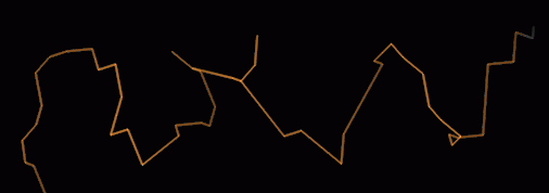
Baton tracing under way
The answer
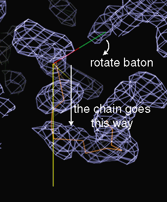
The skeleton is there to show you which way to go
Problems & comments:
It is often easy to place CAs in helices and sheet strands, but is much
harder in loops. It may be helpful to build into loops from both ends,
and leave out the worst bit if necessary. Watch out for clues that you
have got out of register, particularly after building round a loop.
The CA atom do not need to be placed very accurately (and that is usually
impossible). Work fast and fix up problems later.
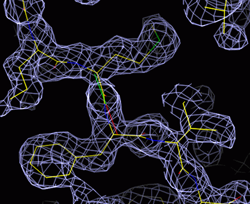
Building the molecule on a CA trace
The positions of the alpha-carbons is sufficient to place all mainchain
atoms and the CB atoms (polynucleotides have more degrees of freedom for
each residue). A library of common mainchain conformations can be consulted
to find the best fit.
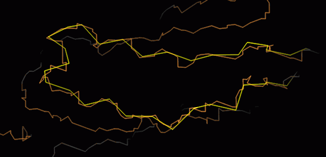
First CA trace along skeleton
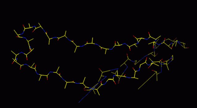
Mainchain fitted to CA guides
Sidechains built in most common rotamer
The O command "lego_auto_mc" fits a series of overlapping five-residue
peptides, then accepts the middle three. Thus the first and last residues
are not fitted (actually they are given junk coordinates, beware), so it
is useful to build one more CA than you can see. "lego_auto_sc" then builds
on each sidechain, in the most common rotamer conformation, for every residue
in the defined range.
This provides a good starting point, but will be wrong in some places,
either because the CA atoms are misplaced, or because the sidechain is
not in the most common rotamer conformation. Automated methods to choose
the best sidechain rotamer may work, but are likely to be defeated by a
wrongly positioned mainchain.
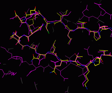
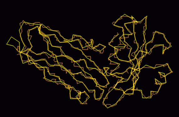
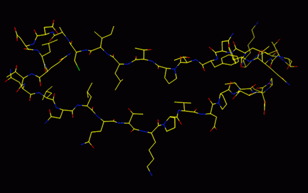
The model may be quite good at this stage, but will have some mistakes
(magenta: final model; yellow etc: model from lego_auto)
Adjustment of model (rebuilding)
Tools for rebuilding
-
Tools based on stereochemical libraries
-
mainchain libraries
lego_auto_mc
see above
lego_loop
offer choice of loop which best fits CA atoms
These options try to follow a set of guide points, CA atom positions,
so errors in these will be propagated into the other atoms.
-
sidechain libraries: rotamers are common staggered conformations
(not all possible staggered conformations are common). Most sidechains
are in rotamer conformations, so these should always be preferred over
alternatives.
(lego_side_chain)
-
torsion angle rotation: preserves bond lengths and angles, but not staggered
angles. Try to keep angles staggered (+-60°, 180°, sometimes +-90°
with sp2 carbons)
torsion_residue (uses torsion dictionary), torsion_general (no dictionary)
-
flip peptide, turn peptide plane over (flip_peptide). Occasionally
the peptide points the wrong way in the initial model and needs to be turned
over: this can be done without major perturbations in the rest of the structure,
since the Psi and Phi angles on either side of the peptide are almost colinear.
-
Free movement tools: move around part of structure, possibly without concern
for preserving stereochemistry. This is often useful when you can see where
to go, but not how to get there. These tools need to be combined with a
stereochemical regularisation, either simultaneously (refi_continuous)
or applied seperately (refi_zone) to restore a sensible structure.
One technique for building recalcitrant bits when you can see where to
place one part is to move the bit you can see into the correct place, fix
it in place (refi_fix_atom) and use the regulariation to drag the
rest of the structure into place. Stereochemical regularisation requires
a dictionary (library) of ideal structural information, which must be provided
for unusual groups
-
move atom (grab_atom, move_atom)
-
move residue or group of residues (grab_residue, move_zone)
-
move fragment, a rigid part of a residue eg phenyl ring, guanadinium group
etc (grab_fragment, move_fragment)
-
move whole molecule, or ligand etc (grab_group, move_object)
Does it fit?
Any movement option can be automated to optimise a best fit between
map density and that predicted from the model, with a minimisation or search
procedure. Automated procedures may go wrong, and put the model into the
wrong piece of density to get a better fit (the density is not labelled).
The human eye and brain is a good guide to a good fit, and the brain is
good at foreseeing the result of possible movements ("if I turn it over,
move it over there and bend it a bit, I can see that it will fit better"):
the computer can only search mindlessly, but can search many possibilities
quickly. One aim of interactive model building is to partition the work
optimally between the computer and the human. Refinement programs are very
good at moving everything a little way to improve the fit, so there is
no point in wasting your time getting everything perfect. On the other
hand, refinement programs will not usually turn a group over, or do any
operation which involves a different atom into density currently occupied
by another atom (labelling again), because they work by minimisation rather
than by a search of possible conformations. Systematic searches, eg of
sidechain rotamers, can do this, but a systematic search of all possible
structure is not possible.
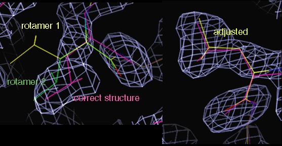
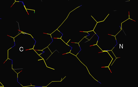
A leucine sidechain changed to rotamer 2, and adjusted into density
Refinement
Refinement itself has been covered in other talks: minimisation cannot
fix major errors, nor build new structure. A major role of refinement is
to produce new electron density maps for examination and for correcting
errors in the model (manually or automatically). Maps from refinement are
typically better than those from experimental phases, and should improve
as the model improves. This is particularly true if the experimental phases
are used in the refinement, which should normally be done, as long as the
dataset used for refinement is the same as that phased: in that case, the
phases are a combination of information from the experiment and the model.
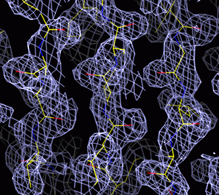
Maps Two main sorts of maps are useful:
-
"2Fobs - Fcalc" type: these show the current best estimate of the electron
density for the structure. This is the map which the model should fit.
(SigmaA-weighted maps from maximum likelihood refinement have amplitudes
(2 mFo - DFc), where m is the figure of merit and D is derived from SigmaA).
-
Difference map, mFobs - DFcalc: this shows the best estimate of the difference
between the true structure and the current model. Ideally, positive density
indicates atoms should be added, negative density that they should be removed
(or moved elsewhere), and a positive/negative pair indicates that atoms
should move torwards the positive density.
During rebuilding, it is useful to display both the 2Fo-Fc map, and positive
and negative contours of the difference map, coloured differently (note
that at least two colour conventions are in use (1) red is positive (2)
red is negative). In general, features in the difference map show that
something is wrong or missing in the model, and the 2Fo-Fc map tells you
what to do about it. In the first round of rebuilding, it may also help
to display the experimental map, at least in difficult regions, since this
is unbiased by the model.
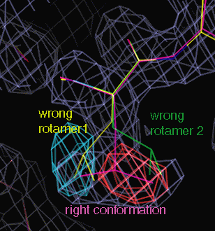
Red: positive difference density; blue: negative
This is a leucine, unusually not in a standard rotamer conformation,
but clear
It is common for parts of the structure to be poorly ordered and therefore
difficult or impossible to model, even if much of the structure is clear.
If no density is present, then that part cannot be built, though density
may sometimes emerge as phases improve by improvement of the model elsewhere.
The major problem is density which is present but uninterpretable: presumably
this represents multiple overlapping conformations, and no good tools exist
(yet) to model such regions.
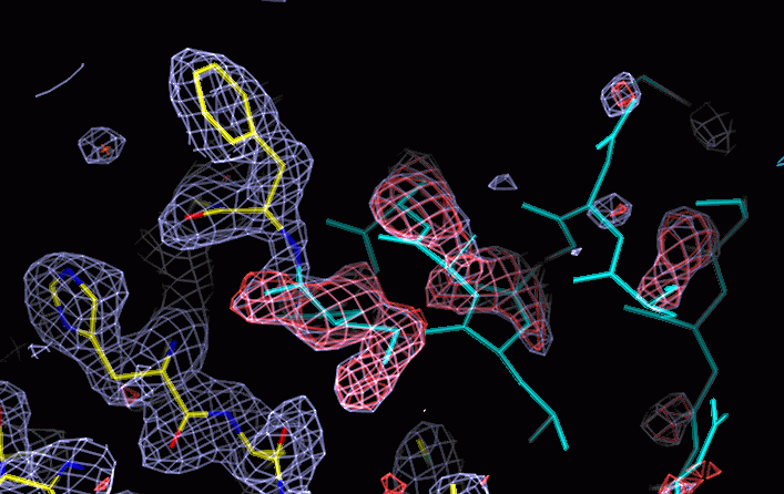
Good density on left, no density on right. In the middle, density which
is difficult to explain with a single model. Red is positive difference
density. The part of the molecule coloured cyan was omitted from the refinement
and map calculation (by setting occupancy to zero) but is modelled from
a second molecule in the asymmetric unit, in which this region is better
ordered.
Water molecules and other UFOs
Waters are an important part of the structure: a well-ordered water molecule
contributes more to the Xray scattering than a poorly ordered part of the
protein. They are clearly visible in expermental maps and particularly
in difference maps, at least at medium to high resolution. At resolutions
worse than 2.8 - 3Å, waters cannot generally be placed reliably:
the free R-factor is a good guide to whether adding waters improves the
model. It is a good idea to inspect each water before adding it, to avoid
putting waters into features which would be better interpreted as other
things: bound ligands, unbuilt or misbuilt protein. With suitable macros
in O, for example, waters can be selected from a peak list very quickly.
Automated water addition (eg with ARP) should ideally be checked manually.
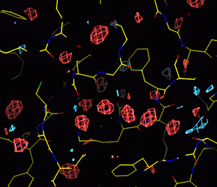
Waters appear as spherical positive features in the difference map
Other features such as expected or unexpected ligands and bound ions
may appear in the maps and should be added to the model when they can be
interepreted (what did you put into your crystallisation mix?)
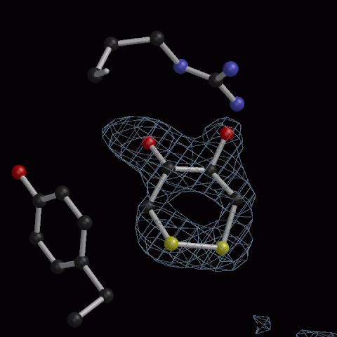
Oxidised DTT, 1.7Å resolution - probably more common than is recognised
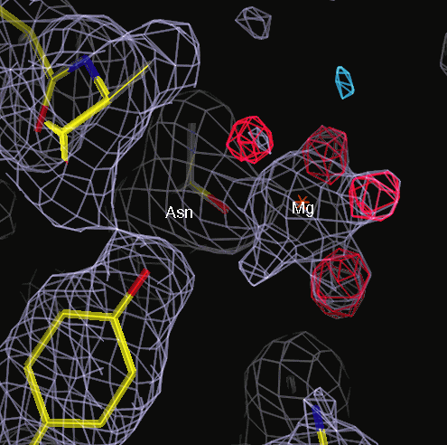
Hydrated magnesium bound to sidechain, ocatahedral coordination.
A water had been built into the Mg++ position.
Four waters in positive difference density, + one in 2Fo-Fc map only
Validation: how do you know that you are right?
During and after refinement, a number of useful checks can be made to find
likely errors in the model and places to examine more carefully. Most of
these checks compare the model to common properties of other similar macromolecules
or small molecules. These properties reflect the energetics of molecular
conformation, so a region of the model which deviates significantly from
normal is either a mistake, or is an unusual high-energy conformation and
thus may be important. Features which are used as restraints in the refinement,
such as bond lengths and bond angles, are not generally useful as validation
checks, since they are likely to be satisfied automatically. Torsion angles
are not generally restrained, so should be checked.
Useful programs:
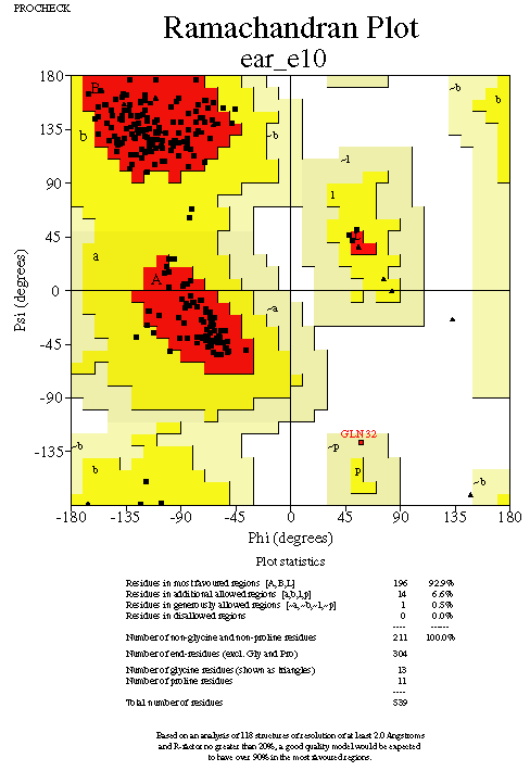
Procheck
(Laskowski et al) Ramachandran plot, sidechain torsions etc
Procheck produces a useful file, .out, which monitors each
residue and flags the ones which should be checked
WhatCheck (Vriend et al) This
does a large number of geometric checks
A particularly useful check is the analysis of hydrogen bonds
for Asn, Gln and His, which can help to get the sidechain orientation correct
Available as a service from EMBL
Mainchain torsions: the Ramachandran plot
The mainchain Phi (N-CA) & Psi (CA-C) torsion angles are highly constrained
by steric hindrance, and any residues falling outside low energy regions
are suspect. Glycine residues are more tolerant of unusual conformations.
Sidechain torsions: Chi1, Chi2 etc
Side chains should normally be a staggered conformation, particularly at
Chi1 (CA-CB). Other conformations are rare. Unresolved multiple conformations
may appear as intermediate eclipsed torsion angles.
When is refinement finished?
Refinement is never finished! The aim is ideally to flatten the difference
map, but at least to leave no interpretable features in the difference
map. Most people refine ad tedium,until they are bored.
© 1999-2005 Philip R Evans, MRC Laboratory of Molecular Biology, Cambridge. All rights reserved.